Welcome! ZZJG VALVE Factory Can Offer High Quality Line Blind Valves And Goggle Valves.
I. General Selection Principles
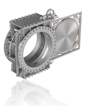
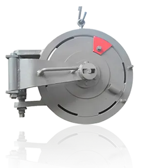
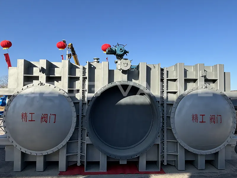
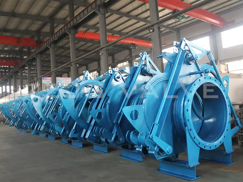
In pipeline systems of industries such as petrochemicals, energy and power, metallurgy, and shipbuilding, spectacle blind valves (also known as figure-eight blind valves) serve as core safety isolation components, playing a crucial role in completely shutting off or unblocking pipelines. They are essential facilities for equipment maintenance, process switching, and safety assurance. The selection process directly determines the valve’s operational reliability; incorrect selection can easily lead to leaks, equipment damage, and even safety accidents. To standardize the selection process and ensure safe system operation, this article focuses on the core selection parameters—pressure rating and diameter—and formulates the following scientific and precise selection guidelines to provide practical reference for engineering practice.
II. Core Selection Parameter Analysis: Pressure Rating
The pressure rating is the limit indicator of the working pressure that a spectacle blind valve can withstand. It is a core indicator for measuring the structural strength and sealing performance of the valve body and is the primary basis for selection, directly related to system operational safety. When selecting a valve, the following requirements must be strictly followed:
(I) Clarify the standard system and distinguish the pressure rating system. Currently, there are two main pressure rating systems in the industrial field. Before selecting a valve, it is necessary to confirm the standard system used in the project to avoid confusion:
Special note: There is no fixed one-to-one correspondence between PN and Class. The selection must strictly follow the standard system specified in the project design documents, and arbitrary conversion and matching are strictly prohibited.
(II) Matching System Design Pressure and Reserving Safety Margin The nominal pressure of the spectacle blind valve must be precisely matched with the design pressure of the piping system. The core principle is: the valve’s nominal pressure must not be lower than the system design pressure. Prioritize selecting a valve with a pressure rating equal to the design pressure, or increase the pressure rating by one level to reserve a safety margin for system operation. Example: If the piping system design pressure is PN16, a PN16-rated spectacle blind valve can be selected. If the system has risks such as high temperature or high pressure fluctuations, a PN25-rated valve can be upgraded to increase safety redundancy.
(III) Considering Temperature Influence and Correcting Allowable Pressure Based on Temperature-Pressure Curves Material strength decreases as the medium temperature increases. Valves with the same nominal pressure rating have significantly different allowable pressures at different temperatures. For example, a PN16-rated valve can withstand 16 Bar pressure at room temperature (120℃ and below), but its maximum allowable working pressure will decrease significantly when the medium temperature rises to 200℃. When selecting a valve, it is essential to consider the actual operating temperature of the medium and consult the temperature-pressure curves of the corresponding material standards. The allowable pressure of the valve must be corrected to ensure it meets the system pressure requirements at the operating temperature, preventing malfunctions caused by pressure overload due to high temperatures.
(IV) Matching Flange Standards to Ensure Installation Compatibility Pressure ratings are closely related to flange standards. Selecting the pressure rating essentially determines the core parameters of the matching flange, such as its size, number of bolt holes, and hole diameter. During selection, it is crucial to strictly verify that the valve flange standard (e.g., GB/T, HG, ASME B16.5, EN, etc.) and pressure rating are completely consistent with the pipeline flange standard and the system design pressure. Any parameter mismatch will result in the valve being unable to be installed properly or experiencing sealing failure after installation.
III. Analysis of Core Selection Parameters
Diameter The valve diameter must be completely consistent with the nominal diameter of the pipeline. This is fundamental to achieving seamless connection between the valve and the pipeline system and ensuring efficient media flow. When selecting a blind valve, the following two points should be emphasized:
(I) Precise Matching of Pipe Nominal Diameter: The diameter of the blind valve must directly correspond to the nominal diameter (DN) of the pipe. For example, if the nominal diameter of the pipe is DN100, then a blind valve of DN100 should be selected. Forcing a match using reducing fittings is strictly prohibited, as this can lead to abnormal medium velocity, increased resistance, or even pipe vibration due to sudden changes in the flow cross-section.
(II) Verifying Compatibility Based on Process Requirements: In addition to the basic matching principle, the compatibility of the valve diameter must be verified in conjunction with the process medium flow rate and velocity requirements. If the process design requires the medium to maintain a specific flow rate at the valve, the valve diameter must be calculated using the flow rate calculation formula to ensure that it meets the requirements, ensuring that the valve diameter matches the process flow rate requirements and guaranteeing system operating efficiency and process stability.
IV. Selection Process Specifications
This guide is formulated based on current domestic industrial valve design specifications and industry-standard guidelines, and is applicable to the selection of spectacle blind valves in the petrochemical, energy, power, metallurgy, and shipbuilding industries. If special operating conditions are encountered during the selection process (such as strong corrosion, ultra-high temperature, ultra-high pressure), the selection scheme should be further optimized by referring to professional design manuals and industry-specific specifications to ensure the safe and reliable operation of the system.
DO YOU HAVE QUESTIONS? WE ARE HERE TO HELP YOU!
Copyright © 2026 Zhengzhou Jinggong Technology Co., Ltd