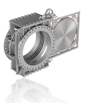
Welcome! ZZJG VALVE Factory Can Offer High Quality Line Blind Valves And Goggle Valves.
Blind flange, in simple terms, is a flange without a hole in the middle, used to close one end of a pipe. The sizes of blind flanges vary under different standard systems. Below, taking the commonly used national standard (GB/T9115-2010) as an example, we will introduce the sizes of some common blind flanges in a relatively easy-to-understand way.
In industrial settings like refineries, commonly used blind flange dimensional standards are divided into international standards (such as ANSI/ASME) and domestic standards (such as GB/T). Dimensional parameters (such as outer diameter and number of bolt holes) vary between these standards, so the selection process must be based on the actual pipeline flange specifications.
I. Core Dimensional Parameters of Blind Flanges (General Definition)
Regardless of the standard, the dimensions of blind flanges are designed based on “compatibility with pipeline flanges” and “withstanding operating pressures.” These core parameters include the following six items:
Definition: This indicates the nominal diameter of the pipeline to which the blind flange corresponds. It is not the actual outer diameter of the blind flange and is used only to identify the “compatible pipeline specifications.”
Domestic standards (GB/T): denoted by DN (Diameter Nominal), with the unit being millimeters (mm). Common specifications cover mainstream refinery pipelines:
Small diameter: DN15 (1/2 inch), DN20 (3/4 inch), DN25 (1 inch), DN40 (1.5 inch), DN50 (2 inch) (mostly used for instrument lines and heat tracing lines);
Medium diameter: DN80 (3 inch), DN100 (4 inch), DN150 (6 inch), DN200 (8 inch), DN250 (10 inch) (mostly used for process media pipelines, such as crude oil and refined products);
Large diameter: DN300 (12 inch), DN400 (16 inch), DN500 (20 inch), DN600 (24 inch), DN800 (32 inch) (mostly used for unit feed/discharge manifolds, such as the crude oil manifold in atmospheric and vacuum units). International standards (ANSI/ASME): Expressed in NPS (Nominal Pipe Size), in inches (in), the corresponding relationship to DN is: NPS 2 = DN50, NPS 4 = DN100, NPS 6 = DN150 (Note: NPS 1 and below are “imperial fractions,” e.g., NPS 1/2 = DN15).
Definition: This indicates the maximum pressure a blind flange can withstand at the rated temperature. It directly determines the thickness and bolt specifications of the blind flange (the higher the pressure, the thicker the blind flange, the more bolts, and the larger the diameter).
Domestic standards (GB/T): Expressed in PN, with units of “Megapascals (MPa)”. Common grades used in refineries are: PN1.0, PN1.6, PN2.5, PN4.0, PN6.3, PN10.0, PN16.0, and PN25.0 (corresponding to low-pressure to high-pressure pipelines, e.g., PN1.6 for circulating water and PN16 for catalytic cracking process pipelines).
International standards (ANSI/ASME): Expressed in Class, with units of “pound class (Lb)”. The approximate correspondence with PN is: Class 150 ≈ PN2.0, Class 300 ≈ PN5.0, Class 600 ≈ PN11.0, Class 900 ≈ PN15.0, and Class 1500 ≈ PN26.0. (Note: The pressure correspondence between Class and PN varies with temperature and should be confirmed in conjunction with the “Temperature-Pressure Ratings” table.)
The actual physical dimensions of the blind flange must be identical to those of the pipeline flange; otherwise, the seal will not be achieved. Core structural dimensions include:
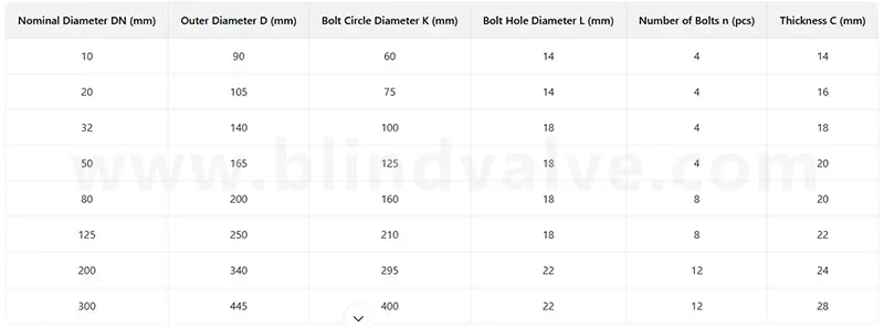
Using GB/T 9123.1-2019 as an example: DN100, PN1.6
Blind flange outer diameter (D): The maximum outer diameter of the blind flange, which determines installation clearance (e.g., whether pipeline spacing is adequate). 220mm
Blind flange thickness (C): The core strength parameter of the blind flange. The higher the pressure, the thicker the thickness (this must be confirmed through strength calculations). 16mm
Bolt hole center circle diameter (K): The diameter of the circle formed by the line connecting the centers of all bolt holes on the flange. This must be identical to the K value of the pipeline flange (otherwise, bolts will not fit). 180mm
Number of bolt holes (n): The number of bolts securing the blind flange to the pipeline flange. The higher the pressure and the larger the diameter, the greater the number. 8
Bolt hole diameter (L): The inner diameter of the bolt hole. This must match the nominal bolt diameter (e.g., an M20 bolt corresponds to a 22mm hole diameter). 22mm
Sealing surface size (d /f): Sealing surface parameters where the blind flange contacts the gasket:
II. Dimensional Differences Under Common Standard Systems (Avoiding Selection Errors)
Refineries may have both domestically produced equipment (using GB standards) and imported equipment (using ANSI/ASME standards). It is important to note the dimensional differences between “same specification” blind flanges under different standards. The key differences are as follows:
Comparing dimensions between domestic standards (GB/T 9123 series) and international standards (ANSI/ASME B16.5)
Nominal diameter designation: DN (mm), such as DN100, and NPS (in), such as NPS 4 (corresponding to DN100)
Nominal pressure designation: PN (MPa), such as PN1.6, and Class (Lb), such as Class 150 (≈PN2.0)
Bolt hole parameters are the same as DN/PN, but with fewer bolt holes and slightly smaller hole diameters. NPS/Class 1 has more bolt holes and slightly larger hole diameters (for higher strength).
Blind flange thickness: For the same pressure rating, the thickness is slightly thinner (e.g., 16mm for DN100 PN1.6). For the same pressure rating, the thickness is slightly thicker (e.g., 19mm for NPS 4 Class 150).
Application scenarios: Domestic equipment and domestically designed pipelines (e.g., atmospheric and vacuum, catalytic cracking); Imported equipment and foreign-designed pipelines (e.g., hydrocracking, alkylation).
III. Considerations for selecting blind flange sizes for refineries
“Exactly match” with pipeline flanges: Dimensions must match the flange specifications of the pipeline (including DN/NPS, PN/Class, and sealing surface type). For example, if the pipeline flange is “DN200 PN4.0 RF,” the blind flange must also be “DN200 PN4.0 RF.” Otherwise, bolts may not fit or the seal may leak.
Prioritize consulting standard manuals: For specific dimensions, consult the official manuals of the corresponding standards (e.g., GB/T 9123.1-2019 “Steel Pipe Flanges – Part 1: PN Series” and ANSI/ASME B16.5 “Pipe Flanges and Flange Fittings”). Avoid relying on experience when selecting. (For example, the outer diameter of a DN100 blind flange in different standards may differ by 10-20mm.)
For special operating conditions, such as high-temperature (e.g., >400°C) or high-pressure (e.g., PN25 and above) pipelines, it’s important to confirm the “thickness add-on” of the blind flange (because temperature reduces material strength, requiring increased thickness to ensure safety). For example, at 450°C, the thickness of a Cr-Mo steel blind flange in PN16 needs to be 2-3mm thicker than at room temperature.
Transportation and Installation of Large-Diameter Blind Flanges: Large-diameter blind flanges larger than DN600 can weigh hundreds of kilograms (for example, a DN800 PN10 blind flange weighs approximately 300 kg). When selecting a blind flange, the load-bearing capacity of the transport channel and lifting equipment must be confirmed to avoid installation problems on-site.
In summary, blind flange dimensions are not a “universal specification” but are determined by a combination of the “standard system + DN/NPS + PN/Class” specifications. The key is to ensure full compatibility with pipeline flange dimensions. In actual refinery applications, it is necessary to first determine the pipeline flange specifications and then refer to the corresponding standard manual to determine the specific dimensions of the blind flange to ensure a secure seal and compatibility with the operating conditions.
Keywords: blind valve dimensions, 10 inch blind flange dimensions, 12 150 blind flange dimensions, 36 blind flange dimensions, blind flange table, blind flanges dimensions, end blind dimensions, flange blind dimensions, rtj blind flange dimensions, spectacle blind dimension, spectacle blind flange dimensions.
DO YOU HAVE QUESTIONS? WE ARE HERE TO HELP YOU!
Copyright © 2026 Zhengzhou Jinggong Technology Co., Ltd